Tuesday, June 11, 2013

First Revised Exhaust Manifold Shell Half

The bottom part is the first one I've made with the changes to the blank template and form block.  I like it.  It has a very even width to the flange.  It is wide enough to trim and fold over the other half.  The corners dis not tear out and the flange is wide enough even in the corners.  There is plenty of straight section at the inlets so they can be trimmed to fit the flanges.   I think I'll make one more before I make the new form block from the ash I bought.

This is great!

Sunday, June 9, 2013

Spot Welder To Weld The Exhaust Manifold Shells Together

 The other day my neighbor, Galen, stopped by to pick up some embroidery.  While his family patiently waited I showed him the progress on the various airplane projects and my efforts to make gas spot weld for the manifolds..  He said they had just stopped at Harbor Freight and saw a spot welder on sale.  I've generally avoided Harbor Freight because a fair amount of the tools they sell are just too cheesy for words. At the same time they can have some cheap deals which I'll admit has a certain appeal to me.  The welder was on sale for $179 so we drove the 40 miles to the nearest one and bought the welder.  My general opinion of their tools hasn't changed as a result, but I couldn't find anything close on line and I don't have a lot of welds to make.

I bought the 230 v model, same price as 120 v model,  since I have the attic wired for it.  It doesn't come with a plug so I stopped at Lowe's and got one to match my outlets.  The rest of the assembly was simple.  It's all metric, think Chinese, and you need a 6 mm Allen wrench to install the copper Prongs.

The idea is you adjust the position of the top prong so you get the pressure you want when the handle is closed against the stop bolt, below the back of the handle.  Then you flip the switch under the handle until the weld is done, as soon as you see red. Spot weld spatter, were eye protection.  The problem I had was that the top prong either is the wrong one or they've started just using the bottom prong for both. I didn't want to wait for their help line to be open to solve the problem so I modified the top prong.

The bottom prong is bent with a 90 degree bend.  The instruction sheet shows the top prong bent 90 degrees at the end but 2 other bends so that the ends are coaxial when closed for welding.  You want both electrodes square to the metal you're welding for good current flow.  Also, I could not get the electrodes to close and the handle to close to the stop.  The bends solved the problems and it welds great.

 One of the things we did at AC Spark Plug to control spot welds, and assure they always formed, was to put a bump on one of the parts being welded.  It controls where the weld forms, that you have metal to metal contact, creates a hot spot to start the weld, and allows you to position the weld with very blunt electrodes which last longer and are easier to make.  I used my Whitney punch with a 3/32" punch and 5/32" die to make these 2 samples on the right.  You want a bump of about 1/2 to 1 material thickness.  Anywhere between these 2 samples will work fine.  You also want just enough pressure on the electrodes to get good current flow, not to mash into the weld puddle.
A good weld should tear out of the steel, not separate.  I finally gave up trying to tear my samples apart.  The welds are very strong.

Saturday, June 8, 2013

Changes to Manifold Shell Blank and Tools

 Now that I've made 3 shell halves I can see where I need to make some changes to the layout of the blank.  I need to have enough steel left along the edges to weld and fold over.  I also don't want a lot of extra steel.  I marked up a shell with changes to make.  The blank under it has the changes.

You can see in the other 2 pictures most of the changes added some steel, especially at the inlets.  The inlets all shortened as the steel was stretched because there is no way to hold the end and make it easy to form into a rectangle.
The only area where the edge was reduced was the bottom edge where the forward inlet tube enters the collector.  That area wrinkled but never pulled into the form block so I reduced it a little.


 I had left an area in the center layer to act as a stop for forming the rectangular inlets.  It was beaten back into sawdust so that was just a dumb idea.  It might have worked if I had wedged a support block under it, but I doubt it.  Because I made the inlets longer, to allow for more shrinkage, I had to cut all that out anyway.  I made some blocks from an ash wheelbarrow handle.  I rounded the edge where the shape transitions from a rectangle to a circle.  There is probably a better shape for this and I'll probably change it when I make a more permanent form block.  I made some wedges from plywood to hold them in position.

 I had 2 pieces of poplar dowel which I used to form the collector section.  They worked fine but were just too soft and were slowly being beaten to death.  I cut off a piece of the ash wheelbarrow handle from Lowe's and drew 1" radii in the top corners at each end.  They gave me a guide for shaping the edge radius with a plane and the belt sander.  The flat back side should make it easier for pounding.  With the dowel pieces, the damage was all caused by the mallet.  With these blocks, not only is the wood harder but the blows will always be on the back side so the face should last much longer.


I finished the ends with a nice radius using the belt sander.  The square end on the long block is for the outlet end.

Sunday, June 2, 2013

Two More Exhaust Manifold Shell Halves

 I've improved the quality of my forming but still need to do a little planishing to smooth out small bumps.  It is only an exhaust manifold but it is visible and should look as nice as is reasonable to do.  I needed a solid anvil to tap on.  After trying a lot of loose dollies I realized that if I just clamped my ball tool to the deck railing I'd have what I needed.  It works great.
I now have three shells halves ready to trim for welding.

I need to make a pattern for trimming and a form block for bending up the edge of the top shell 90 degrees before welding.  I also need to work out the welding process to create little spot welds.

Monday, May 27, 2013

First Good Exhaust Manifold Shell Half

 I keep thinking I can do this with a few tools.  Some how it never seems to work that way.  In fact I have ideas for more tools to make this all work better.  I need to get a used wooden baseball bat.
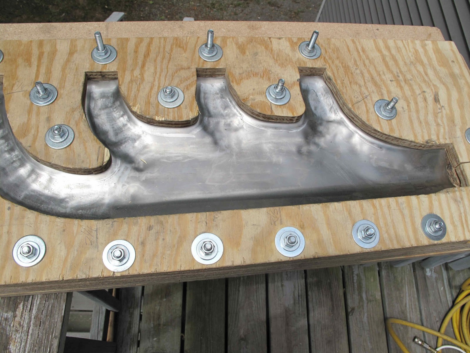
 Part of the trick to this is which bolts to have tight and which loose.  Tight bolts hold the metal from moving and allows the metal to be stretched.  Loose bolts let the metal slide so you don't have to stretch it too much and fracture the steel.

The first tool is the rivet gun and narrow tool.  the smaller tip area gives higher psi. I start at the intersection of the tubes and work up the edge of each tube, but not along the long straight bottom.  I then go across the bottom of the tubes and work toward the top to get the forming started.


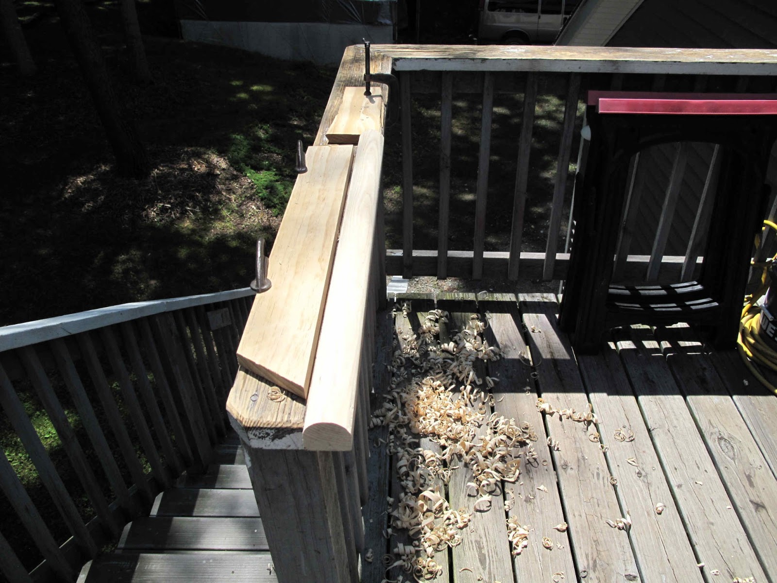
 The bottom gets formed with a piece of 2" dowel, until I get a dead baseball bat.  It forms the bottom as a nice straight curve and pulls the steel out of the form block rather than stretch it, which would be too much work and it would end up wrinkled.

There is a wrinkle starting at the top because I went to far with the bottom dowel.

 The top gets formed with a short piece of dowel.  If I had worked between the 2 dowels with smaller deformations I think this would have come out smoother in the radius going to the outlet.

We'll see how I do on the next one.  At this point it's time to go back to the inlet tubes.


 As I form the inlet tubes the inlet itself closes in because the metal slides in the block.  Every so often I stop and use the dolly to stretch the excess so the bend doesn't get out of control.


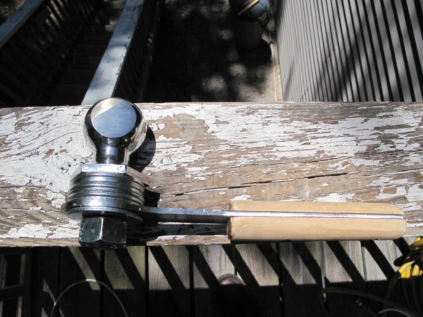
 Once the tube is to the correct depth near the inlet, the actual inlet needs to be formed.  That's where the modified bolt comes in.  I can drive it down to square up the inlet and get it to the right depth.


 There is still more work to be done forming the tube and I don't want the inlet to close back up, so I made some blocks of oak to drive down in the inlet. By clamping it in place while I work on the rest of the tube, the metal can't slide in.  I also tighten the 3 bolts right at the inlet.

It turned out the anvil on the 6" c-clamp was to big and the clamp kept sliding off the edge of the plywood.  The adjustable clamp worked better.  Even though you can't get it as tight.


 All the forming is done except the outlet.  I couldn't get it to form a nice radius so I decided to make a tool to pound into the block to form it in one hit.  I wanted Oak but I settled for some treated Yellow Pine from a piece of 4x4.  I sawed it to 2 3/4" wide but put a 1 1/8" radius on each corner.  The idea was to over bend the radius a little so it would spring back to 1 3/8" radius.  It worked great.  Problem solved.

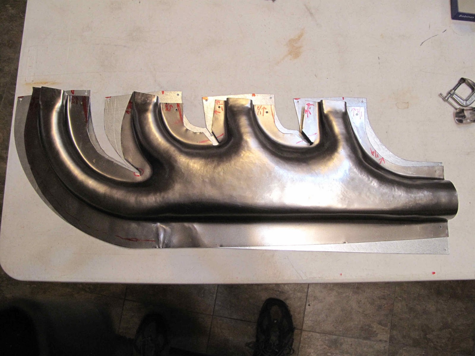
 It came out great.  There is a little roughness in the tubes, but I like it.

 The inlets came out the right size without any cracks or tears.
 The one mistake I made was to work the tubes from front to back.  I should have done the front tube then the back tube, followed by the middle tubes.  It all slid slightly toward the front.  You can see from the blue lines, which started at the edge of the form block, where the steel slid and stretched.

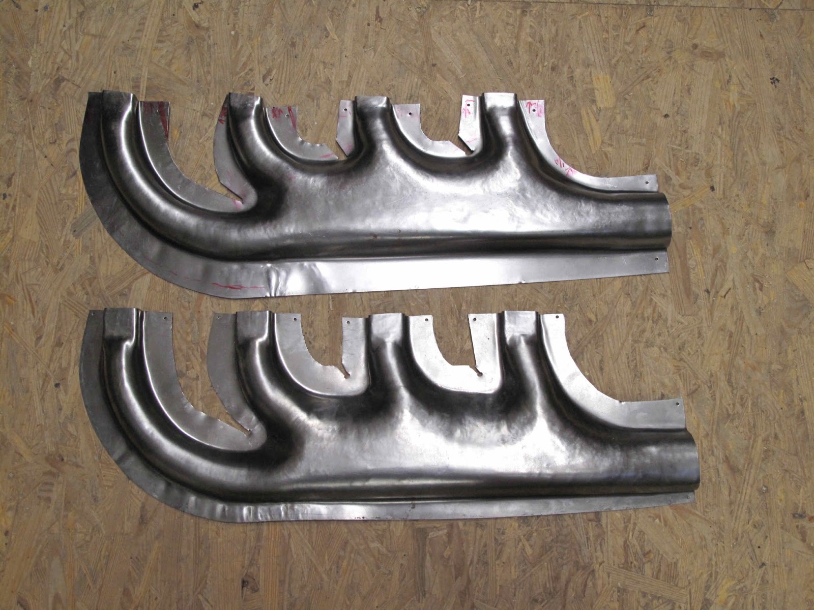
 Here is the comparison of the formed shell with the blank.

You can see from the top view how well it worked to let the steel slide into the bend along the straight bottom edge.  The cuts into the corners where the tubes join worked very well to let the steel slide into the tubes.

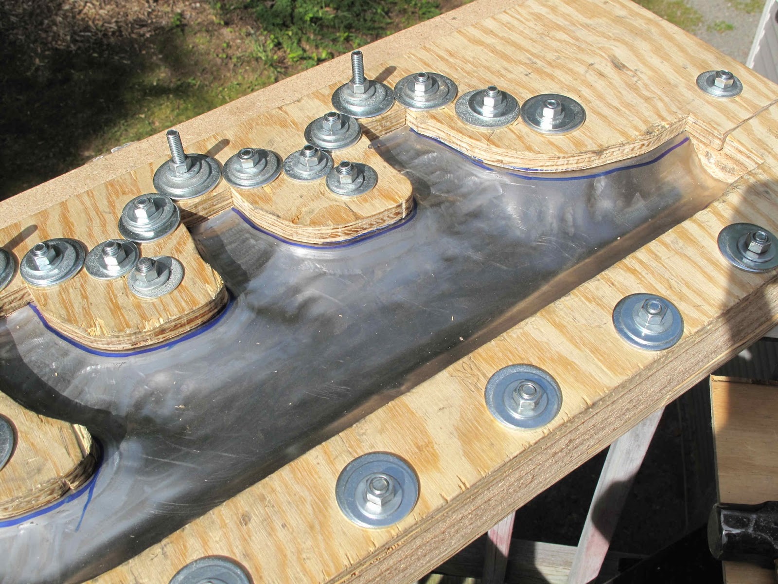
With a good Left Hand Bottom shell I'm ready to make the opposite shell.  I worried that my plan to swap the top and bottom pieces of plywood would never work because there are 32 bolts to align which meant the holes in the block had to be almost perfectly perpendicular to the block.  As it turns out the Shop Smith is up to the task.  I drilled the bolt holes 1/64" oversize so the bolts would go in easily but still be snug.

They all fit perfectly.  I didn't have to re-drill a single hole.

Time to make another shell.

Saturday, May 25, 2013

Some Better Tools For Forming The Exhaust Manifold Shell

 From the first piece I learned I needed a piece of wood under the flat section of the collector so It would end up flat not bulged in the center.  To do that I needed a piece of wood which tapered 1/4" form the end of the first inlet tube to the outlet end.  I decided to use the scrap cut from one of the layers since it would fit and stay in place without anything to hold it in position.  I need to be able to flip it over to do the other side of the shell.  To taper it I drew a guide line on each edge and the used a 24 grit disc on the sander.  I smoothed it a little with the belt sander.

 I started the forming with the along the edges with the narrow tool and then used it to start the shaping of the inlet tubes.


 I used some 2" dowel to make some tools to form the collector area so it would have less dents when all done.  I left the lower bolts loose while forming the collector so the steel would slide rather than just stretching.

 I decided to make a better forming tool using the 2 5/16" ball.  Unfortunately it has a 1" threaded end.  The other balls are 3/4" as is the hitch insert I used as a handle.  I decided it was easier to make a handle then to modify the hitch end.
 I used some scrap 3/16" x 3" steel from making the WACO NINE nose rib forming tool.  I sawed out a handle about a foot long with a 1 1/4" wide handle to fit some dowel I have.  I made the ball end big enough to fit the base of the ball and cut a 1" hole with a hole saw.

For the handle I drilled 4 holes in the steel for screws to pass through.  I split the dowel and ran 2 screws from each side though the steel into the other half of the dowel.  I rounded the ends of the dowel for a nicer job.

I stacked enough 1" washers, from Tractor Supply, to get the nut flush with the threaded end of the ball.

 The ball shape I wanted was more oval than the first ball.  I ground flats on the 2 sides working to keep them equal distance form the center by eye and by making the flats the same diameter.  I ground until the ball was 1.74" wide.  I used the 24 grit disk on the disc sander.  I was able to see what I was doing better and the 24 grit cut much faster.  I still had to cool the ball from time to time.
Next I radiused the top on the 2 sides with the sander.

 I then worked the top of the ball to a nice even curve from front to back.
With these curves established I blended in the corners.  To finish it smooth I used the belt sander.  There is an area at the top between the roller and the backing plate where the belt is unsupported.  It works great for blending  with less sharp edges on each pass.  Next I lightly filed off high edges and then worked it in the palm of my hand with a piece of 120 grit belt to smooth it better.  I finished it with Scotchbrite.

It's way better than the first one.

 I turned the ball at an angle to make it comfortable to hold with the axis of the ball in line with the inlet ends of the pipes.

As you work down the pipe, holding the ball at about the same angle makes the ball naturally wider to fill the shape of the tube.


It really works great.  This is what the first tube looks like after the first rough shaping pass.  Very cool!