Wednesday, April 16, 2014

Exhaust Manifold Heat Box Patterns

Based on the OX-5 parts list, under the right hand exhaust manifold there was a heat box.  I would assume it was for Carburetor Heat to stop ice forming in the carburetor.  But, according to Ted Barber, in his book The Barnstorming Mustanger, the WACO NINE he flew herding Mustangs in Oregon did not have Carburetor Heat.  It was only when he got a newer plane that he learned about Carburetor Heat.  I'm not sure what the heat box on the Curtiss exhaust was used for.
The picture of my WACO NINE from 1927 clearly shows the heat box on the right exhaust with a piece of tubing going into the cowling.  Nothing in the WACO drawings shows a Carburetor Heat arrangement of control to operate it.  I'm adding the box to both manifolds and we will have Carburetor Heat.  I wonder how someone with straight pipes gets Carburetor Heat?
The lack of Carburetor Heat appears to be one of the reasons this engine developed a bad reputation.  The other reasons, according to Parks Air College, were the need for Miller valves, better fits assembling the engine, and better oil.  They flew 1,000 hours between overhauls doing flight training in 1929.  I believe the coil in the magneto was also a problem, shorts and opens.
 One of the planes at the Airpower Museum has heat boxes on both sides but they are not connected to anything.  They are very nice looking stampings in a streamlined shape.  The streamlining seams excessive but I believe it was actually easier to stamp the parts in this shape because of how the steel stretches.
They are very nice looking but I believe they are a little small to get enough temperature rise.  The inlet is on the engine side so the air has to flow around the exhaust to enter, giving a little more heating.  They also placed the outlet near the edge opposite the inlet to give as much time for the air to heat as they could in such a small box.
The outlet pipe is spot welded to the box and the box is spot welded to the lower shell.


 I decided to make the box with curved sides but welded corners.  It is under the exhaust after all.  I could form such a nice box and make the rights and lefts from the same formed box by sawing off the inlet edge.  I think for the few I need it will be easier to weld the corners. The box is gone on my RH manifold.  If I had a known original box to duplicate I might form them.
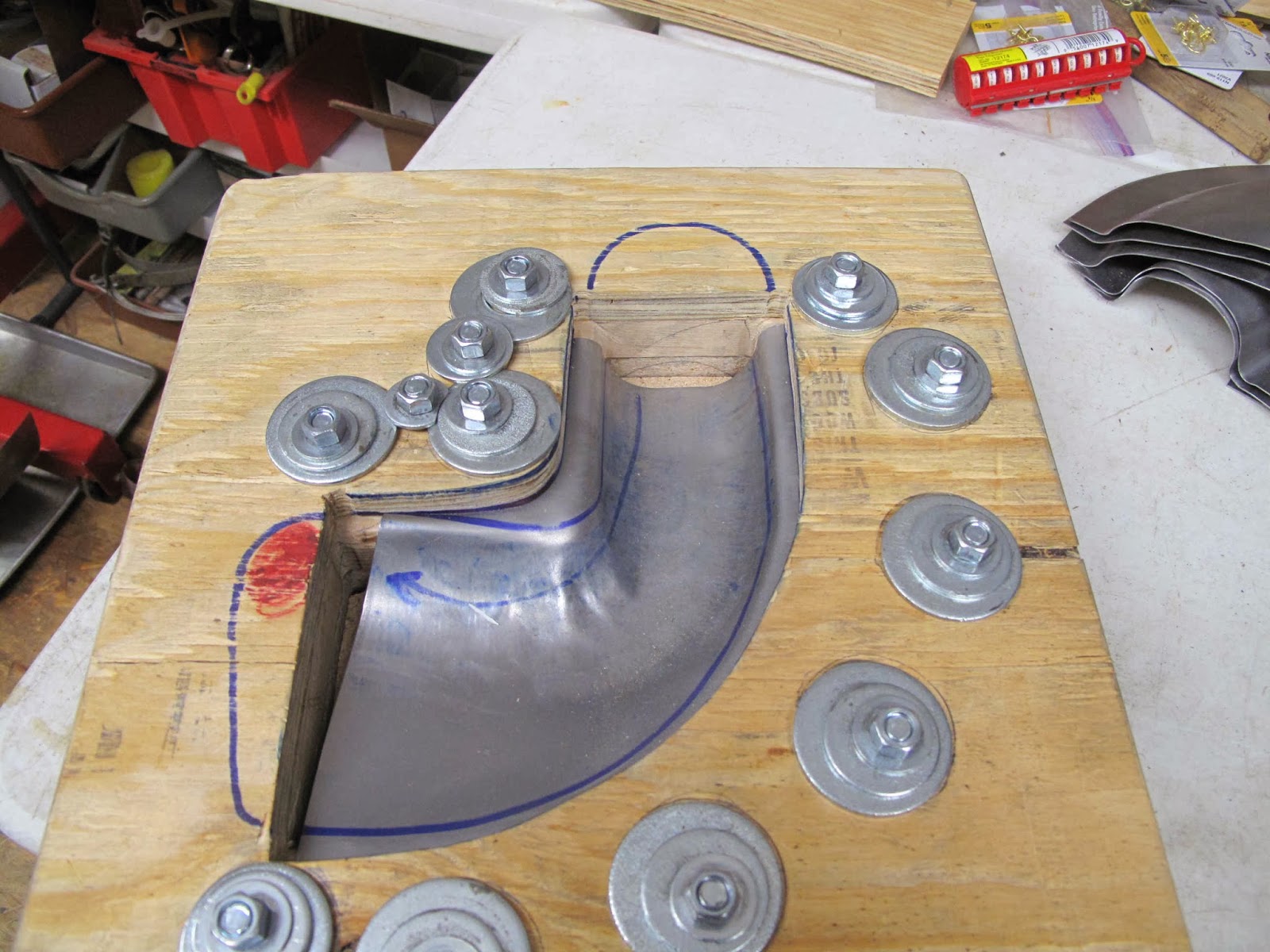
I started by deciding what size to make the box and the made cross section strips from poster board to work out the size of the blank.  Clearly I could have done this on the CAD system but sometimes its more fun to just make patterns.


 I made it a few inches longer and place the outlet where it appears to be on my NINE.


 To give the air more time to heat up, I also decided to add a baffle in front of the outlet tube.  The box is 1" deep and the baffle will leave a 3/8" gap between it and the manifold.  It also only goes half way down each end so there is plenty of room for air to flow to the outlet without restricting the flow.
I'll  gas weld the corners and the outlet tube, then spot weld the baffle to the inside of the box.  The bend in the baffle is to direct the flow around the ends to add more time for heating.

 Hear is the position inside the box.

I made galvanized patterns from the paper patterns.  The baffle is at the top and a blank the size needed to form the outlet tube is in the middle.  I'll spot weld it closed to make the tube.

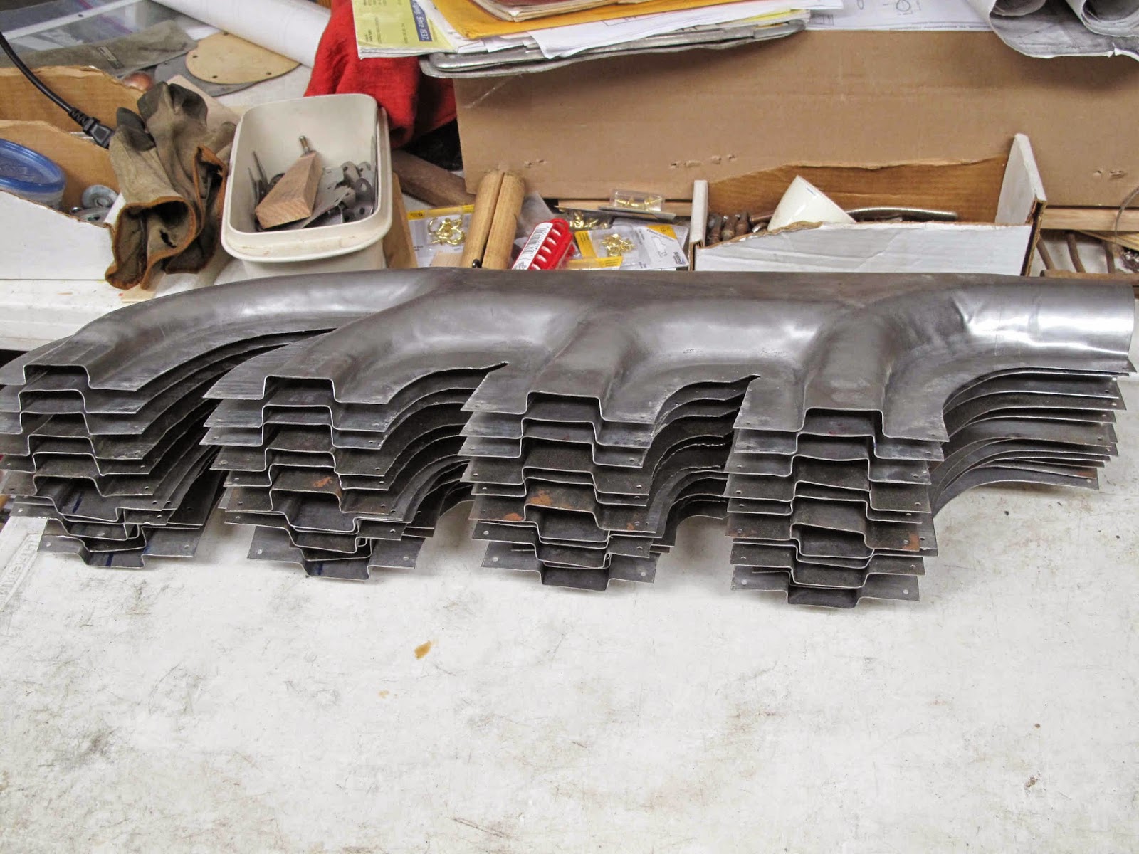
Now I need to make the blank pieces.

Sunday, April 13, 2014

Exhaust Shells Complete


 I've made enough shells to make manifolds with the outlet elbows for 3 engines.  It's actually an impressive pile of parts.

The next part to make is the heat box which gets spot welded to the bottom shells before assembly.

Then I have some patterns to make to trim the excess steel along the edges, and some fixtures to hold the inlets in proper alignment while welding.

Exhaust Outlet Elbow Shells


The outlet on the exhaust manifold goes into a 90 degree elbow.  The inlet of the the elbow is round, about 2-3/4" diameter, and the outlet is teardrop shaped.  The wide end of the teardrop is toward the front of the engine, like a streamlined strut.  The construction is the same as the shells for the manifolds.
The form block was made by the same method as the new block for making the manifold shells.   The center layer is particle board and the outer layers are made from blocks of ash glued together and to the particle board core.
To figure out the shape of the blank I assumed all the shaping would be done by letting the steel slide in the blocks rather than by stretching the steel.  Strips of card stock were used to simulate the pulled metal and the flattened to mark the flat pattern,
With the flat pattern drawn on the block, the bolt hole locations were worked out by using the washers to see where pressure would be applied.

I sheered the blanks and then decided to try cutting them to shape with band saw.  It worked great, much faster than snips or the nibbler.

I leave a gap at the ends.  If the blank moves a little it won't hang up on the block.

As with the manifold, I used the scraps from the center layer and the plywood clamp block to make a tapered block to limit the depth the metal forms into the block.

The parts come out very well with about 20 minutes work.

One thing I had to work at was, to remember to stay on the leading edge side of the outlet to have the teardrop going the correct direction.  I marked the block but found that drawing an arrow along the forward side worked as a better reminder.
I also made a large block from the ash to form the inlet end.  It has the shape like the block I made for the outlet of the manifold.  I also put a radius on one edge so it wouldn't crease the steel.  The other edge is square to fit snug at the ends.


I start with the big block and get the shape started with the bolts tight.  Then I loosen bolts as needed to get the steel to slide evenly from the edges.

The steel pivots on the inside flange as you work it.  You pound the inlet down and the outlet moves up.  To stop that I use a block of wood and a large c-clamp to hold the one end while working the other end.


With a couple of other wooden tools the shape is quickly formed.

Once the shape is correct the outside edge is lightly shaped to form a tight radius .

Occasionally wrinkles form in the inside corner which can not be easily worked out.  The trailer hitch ball works well to shrink them back.


The blunt tool with the rivet gun works well to smooth the blend from the radius to the teardrop.

With the shaping done you can see the teardrop.

The inlet end will get rounded better when the 2 halves are welded.


As with the manifolds, any slight bumps are corrected with the planishing hammer and the trailer hitch ball.

The opposite half is made in the other side of the block.

They come out very well.