Saturday, January 31, 2015

Exhaust Manifold Inlet Flange - Cutting Ideas


 I have all the welding finished on the manifold shells.  It's time to make the inlet flanges which hold the manifold on the engine.  The ones on the old manifold seem to be 1/8" thick.  They also all bent, too thin and weak.  John made his 1/4" thick, which seems thick to me.  The WACO drawing shows them 3/16" thick.  I think with a slight redesign of the shape around the bolt holes I can make them strong enough to reduce the bending.  We'll get back to that in another post.  I've bought some mild steel bar stock 3/16" thick and 1 1/2" wide, perfect for our flanges.
 One of the problems making these is that they are mounted at an 18 degree angle, with the top angled away from the engine.  To make them fit properly on the manifold inlet tubes, the top and bottom of the rectangular hole are cut at this angle, not perpendicular to the face, like all the other edges.  I would love to know how the factory did it.  I assume they were stamped in a progressive die.
 My idea is to cut them with my spiffy Dillon Mk III (now Cobra Torches) oxy-acetylene torch.  In 20+ years I've never used the cutting attachment so this is a great chance to play with it.  The literature says it cuts better than a plasma cutter.  Like I ever believed that.  I set it up and practiced a bit with it to see how fast to move while cutting, etc.

I then clamped a piece of angle to my practice piece of 3/16" steel to use as a guide to simulate a fixture for guiding the angle of the torch cut.


 With the torch resting on the the angle I made a couple cuts across the steel.
I was shocked how clean and even the cuts were.  The band saw doesn't cut this well.  I need to build a fixture to use the torch to cut the flanges.

Thursday, January 29, 2015

Folded Edge On Exhaust Manifolds

The next step is to form an edge along the outside of the seam between the 2 shells.  The edge of the upper shell on the original manifold was folded 180 degrees so it covered the edge of the lower shell, leaving a smooth finished edge.  The welding holds the shells together so this just creates a smooth finished edge.

I've had a lot of ideas for how to do this.  Slowly the complicated ideas have all been abandoned.  The easy way is probably how the factory did it, just a hammer and a dolly.


There are a variety of straight sections, inside curves and outside curves.  While the details are slightly different for each, the method is basically the same, fold the upper edge over the lower edge and hammer it tight on the dolly.
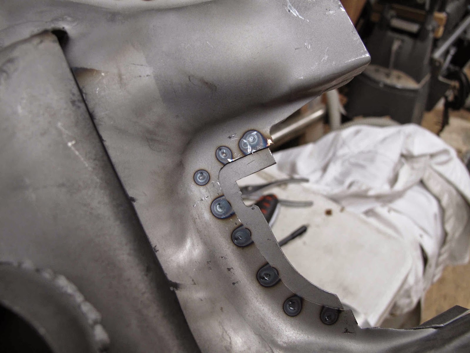
On thing I quickly realized was that some of the ends of the shell needed to be trimmed. You don't want the folded end to stick out past the welded seam after folding.  The edge on the left of the tube will fold without sticking out past the end, while that on the right needs to be trimmed first.

The ends were trimmed with the snips where the angle formed at the end of the lower shell was less than 90 degrees.


The spot welds are quite strong and the steel at he edge is still soft since it has not been worked like the tube areas.

The first step is to hammer the edge down at about a 45 degree angle.  This gets hammered around the lower shell, in steps of about 30 - 45 degrees, until it is past 90 degrees.


I'm using a Handy-T Dolly from Fournier ( a present from the grandkids).  It fits the 3/8" radius in the corner of the shells so it won't nick them.

With the shell resting on the dolly the fold is completed and then hammered tight.


For the inside curves I used a round hammer.  This hammer has a flatter curve than my ball peen hammers.

Again you just work back and forth over the length of the seam slowly bending it over.  The steel is soft enough that it stretches without cracking,

Once it's past 90 degrees I move to the dolly to finish the fold in 30 -45 degree increments until it is flat, then tighten it.

This was the longest inside curve and it formed just fine.
The outside curve is done with the flat side of the hammer working the length of the curve in 30 -45 degree increments.

The edge looks wavier as you work because the outside edge is longer and the steel needs to be shrunk to make the fold.


As you approach 90 degrees the edge is shrinking and getting less wavy.


Again, once the edge is past 90 degrees it can go on the dolly to slowly work down tight.


You can see how trimming the end of the upper shell left a nice end to the fold.


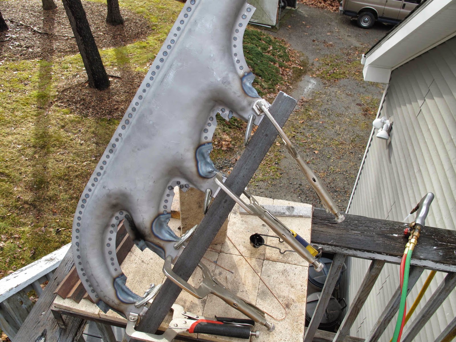
For the long straight edge I used the seam pliers to slowly work the bend to about 90 degrees and then hammered it, along with the long outside curve on the forward tube.

It took less than 30 minutes to fold all the edges on my first shell.

Simple still seems the best way to make things.

Sunday, January 25, 2015

First Outlet Elbows Welded to Manifolds


 I got a little smarter about how to hold the heavy assembly while welding.  The vise worked great for a third hand.

The vertical took a little work to balance it but once i figured it out it worked great.

 I didn't weld the inlets all the way to the end because I still need to fit the flanges.  I'll finish the last bit of the seam when I weld on the flanges.


All the shells are welded and the inlets look good, well aligned and squared.

On to the Outlet Elbows.


 I had a lot of ideas about how to assemble these and fit them to the manifolds.  After some experimenting using lots of clamps I realized the easy way to do this was to weld the outlet half.  This left the inlet end loose enough to fit over the manifold without all the clamps in the way at the other end.

The first one I welded I used clamp blocks and a c-clamp to hold everything tight while I welded the overlap.


 For the rest of the elbows I used the clamp blocks and the outlet tool to more carefully fit the shells to the tool.  Like I did with the manifolds, only without the strap clamp.  I hammered them to a snug fit on the tool and they all fit the manifolds just fine.

 When I welded the overlap I tacked the center of the top and bottom to hold the elbow straight with the manifold and with the seams lined up.  I then started at the tack and welded 1/8th of the circumference.  I then rotated to the other side, started at the tack and welded 1/8th again.  The back to the other side started at the tack and welded 1/8th, continuing until all the seam was welded.

I don't know if it mattered but I didn't want to cause any misalignment by welding one side and then the other.
 I've got 2 finished and all the elbows fitted, ready to weld on the last 4.

They seem bigger then the old one which was missing most of the elbow.

This is fun.

Saturday, January 24, 2015

Gas Welding Exhaust Manifold Joints


 Before clamping the shell assembly back in the alignment fixture there are some inside corners which need trimming.

The finished edge is created by folding the longer flange on the top shell over the shorter flange of the bottom shell.  It's not possible to do this in the tight inside corners.  The factory just trimmed off the longer flange in these corners and gas welded the corners.

I used the nibble to clean out the corner.

The shell was then pushed back onto the inlet alignment fixture and clamped to hold the inlets tight to each block.

Before welding I closed up any small gaps.  It makes welding easier if the edges of the 2 shell halves fit snugly together.

The steel is soft enough it is easily moved with light taps of a ball peen hammer.
 The hardest part was propping the heavy fixture and shell at angles which made welding each seam easy.  I believe the combination of spot welds on the flanges and gas welding the small areas was faster than welding the entire edges.

You can see from the heat affected zones where the 7 seam were gas welded.

Next will be to weld on the outlet elbows.  We're getting there.