Thursday, February 26, 2015

Exhaust Manifold Flanges - Inlet Side Cut Fixture

The 2 side cuts for the inlet openings needed a fixture to get a straight cut and to hold the torch at an 18 degree angle while making the cuts..  For the top and bottom cuts the angle is formed by tipping the plane of the cut 18 degrees from perpendicular while holding the torch perpendicular to the flange in the plane of the cut.  For the sides the 18 degree angle is in the plane of the cut while the plane of the cut is perpendicular to the flange.

 Just like the other fixture I'm using the vise to hold the fixture so again I started with a piece of steel angle clamped in the vise.  The flange sets on the angle while cutting.


I cut 2 slots in the piece of angle to provide clearance while making the cuts.  I left the center piece so I can clamp the flange in place while cutting.

 To locate the flange for cutting I made a pocket for the flange to set in.  I had wanted to use a pin in the bolt hole as a stop side to side like I did in the other fixture but there wasn't enough room.  The side cuts are too close to the bolt holes.


The pocket will get held to the angle by the screws which hold the roller guides in position.

 As with the other fixture, the side roller guides are pieces of 0.050" steel with slots for the screws to allow side to side adjustment.

In this case I will use the left hand guide for the cut on the left side of the flange and and the right guide for the right side cut.

 With the other fixture the the side rollers are adjusted to tip the cutting tip to the side.  With this fixture the front (side) rollers are adjusted even to hold the tip square.  To get the 18 degree angle the rear roller needs to be 1.71" lower than the front rollers.

To do this I made an "L" shaped table which is attached to the back of the angle.  The vertical slots allow the height to be adjusted to get the 18 degree angle.  The side slots allow the side guides to be adjusted to position the rear roller.  They also hold the 2 pieces together to form the table.


 As with the front roller guides the rear roller uses the left hand guide for the left side cut in the flange and the right guide for the right side cut.

I need to adjust all these movable parts, wait for the current snow storm to end and then try this out.

Monday, February 23, 2015

Exhaust Manifold Flanges - Inlet Angle Cutting Fixture


This is another project where I had a lot of ideas on how to position the torch to cut the 18 degree angle on the upper and lower edges of the inlet hole in the exhaust flanges.  In the end I decided to use the cutting guide which came with the Dillon Torch (now Cobra Torches)and build a fixture to guide the torch.  The first issue was the 18 degree angle.  The 2 roller guides are independently adjustable so you can set the torch to cut at an angle.

To set the angle I needed a gauge.  I drilled a hole the diameter of the copper cutting tip in a piece of plywood and drew a line at 72 degrees to the center line of the tip and 1/16" beyond the end of the tip.  With this gauge slipped snugly over the tip it was easy to set the rollers to the 18 degrees needed and maintain the required tip clearance from the steel.


The next problem was how to keep the copper cutting tip perpendicular to the steel in the plane of the cut line.  I decided a roller attached to the handle would solve this.  I had a roller I plan to use for another project and it was snowing out so with a couple modified U-bolts it's clamped to the handle of the torch so I can still operate the cutting button which turns on the Oxygen.

To position the roller up or down to square up the tip angle you just adjust the nuts in the 4 corned of the roller.  To measure the angle of the cutting tip to the roller I made another wood block to slip over the tip and used the square to adjust the height of the roller.  It rolls nice and smooth.


To control the line of the cut you a need an edge for the rollers to roll against.  I thought one edge would work for the front and rear rollers.  I found it all tracks better if there is a guide for the front rollers and one for the handle roller so that the line they follow is perpendicular to the axles of the front rollers.

Some experimenting with clamps and steel showed it was easy to make separate roller guides and to use a piece of angle as a stop for the end of the cut.  When the rollers hit the stop just release the Oxygen button and lift the torch.  I think it will work.

 I forgot to take pictures as I made the fixture so here's an explanation of what I made.  I needed a base that I could clamp in the vise to hold it while cutting.  I used a piece of 2" angle so it would be wide enough to support the flange while cutting.

The widest 3/16 steel I can get locally is 3" so I used a piece of 1" and a piece of 3" to make the base.  The 3" piece is screwed to the angle so the roller can smoothly pass over them.  The 1" piece is bolted down along with a piece of 1/4" steel which guides the roller.  I decided I needed a track for the roller so I used a piece of 1/2" angle for the other side of the track.

 I also used the 1/2" angle for the stop for the front guide rollers.  For both of the guides I made the bolt holes as slots to allow adjustment.
 The 2" angle makes a base for the flange to set on while cutting while leaving clearance for the slag to blow clear.  I threaded a bolt into the flange, put a nut on the bottom and cut off the shank to make a locator pin.

You place the flange in the pocket and slide it against the stop.  The flange just sets there while you make the cut.


 To guide the front rollers straight while making the cut I made some guides from .050" steel.  The right hand guide wraps around the base plate because there isn't room on top to mount it.  I would have needed a 5" wide piece of steel to have mounted it on top.

On both the left and right guides the screw holes are slotted to allow adjustment.  I played around rolling the torch quite a bit before cutting parts to get all the adjustments where I thought they would need to be for this to work, which it does.


 Yes that's snow in the background but it's about 50 degrees outside and sunny so it was a great day to cut low carbon steel.

The fixture is in the vise which is on the fire bricks.  I placed a piece of steel to catch the slag.  The mess from my first experiments with the cutting torch is still stuck to the bricks.  Let's face it, it was molten steel as it was blown clear of the steel.  I probably could have guessed it would stick to the bricks.

The flange is setting in the fixture ready to cut.

 The torch is in the, forward, cut start position.

It's adjusted left to right to cut tangent to the outside of the corner holes.

I found that it cut better if I started in the back, stop position, then without the extra cutting oxygen, slowly move forward to heat the flange.  Then pause in the start position until the hole edge starts turning red.  Once the hole starts turning red squeeze the oxygen button and start slowly pulling back to the stop position, better a little slow than too fast and loose the cut.  When the rollers hit the stop release the button and lift the torch.


 Lift the flange out with a pair of pliers, red hot steel, flip it left to right, re-position it and make the next cut.

The slag from the first cut is on top so it doesn't get in the way.

A quick whack with a hammer shears off the slag.


A very clean part with crisp straight cuts.  On to the side cuts.

Wednesday, February 18, 2015

Exhaust Manifold Flanges - Drilling Holes


To cutout the center opening I decided to drill the 4 corners with a 3/16" drill.  To locate these holes I made a small fixture for center punching all the holes.  It's made from 3/8" bar stock 2" wide.  It has 2 3/16" bolts on the edge to locate it along the edge of the 1-1/2" bar stock.  By turning the bolt heads slightly you can align it very precisely with the bar stock.  I only center punch 2 of the corner holes and the flip the bar stock over and mark the other 2 holes.  More on that later.


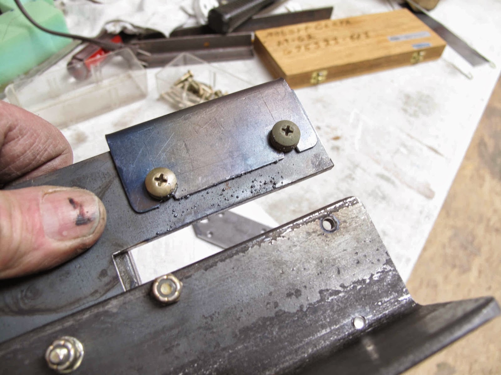
The mounting holes are oblong to fit on 5/16" studs.  One hole in the fixture is centered on the outer end of this hole.  The other is just touching the edge of the inside of the hole.  The idea is to drill the 2 holes in the flange with a 3/16" drill, then drill the outer one with a 5/16" drill.  To finish the hole I plan to use a 5/16" rat tail file and just file down to the bottom of the inside hole.
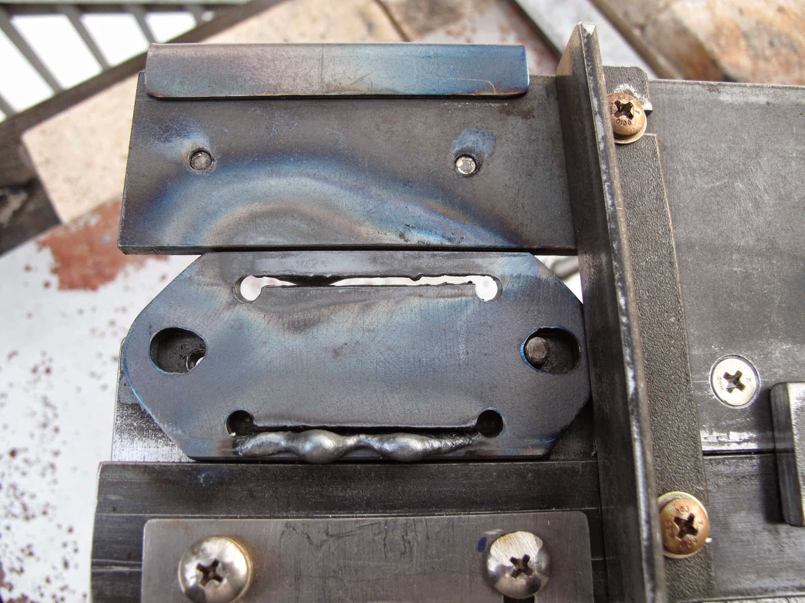
The inside hole also serves as a pivot for belt sanding the radius and flats on each end of the flange.  This shape should simplify making the ends and give them a little more steel to stiffen them when bolted to the cylinder.

The first step is to clamp the fixture to the strip of 3/16" x 1-1/2" steel.

Using a 3/16" transfer punch the centers of the 6 holes are marked on the steel.

The end of the flange is scribed on the steel.  Before I clamped the fixture on I used a blue felt marker to highlight this area.  It's easier to see the scribe line when cutting the ends.


I don't want to wear out my transfer punch so I only make a light make on the steel and then hit the marks with a center punch after removing the fixture.  I've gotten in the habit of using the center punch after marking holes with a prick punch.  The center punch has a shape the same angle as the drill so the drill centers in it better.

I used the transfer punch to locate the fixture, in one of the hole punches, to scribe the opposite end for cutting.

With the first part ready to drill the fixture is positioned to mark the next piece.  The flanges are 3-1/2" long and I'm using a 48" piece of steel so I spaced them every 3-5/8" from each end.  You get 13 pieces from the strip of steel.


With the parts all marked the next step is to drill the 3/16" holes for the mounting holes.  I like drilling thin stock like this with a center drill.  It's to short to flex, so you can control the location better, and it drills it's own pilot hole.

To keep the piece flat on the table I de-burr each hole after drilling.

I need to locate the pivot hole over a 3/16" bolt so after drilling the holes I opened them up slightly with a #11 drill.  The hole fits snugly over AN-3 bolts.

Having the holes enlarged to #11 also allows the transfer punch to to be used to locate the fixture to mark the other 2 corner holes for the inlet opening.  I've got one punch in a hole and am using another to mark the holes.
Because the corner holes are drilled at an 18 degree angle the center mark was located farther from the edge to allow for the angle.

I made a wooden fixture to hold the steel while drilling at the 18 degree angle.  At first I only made it wide enough to hold a part.  It was easier to hold a strip with a few parts on it so I widened the area with the angle on it and drilled a clearance hole for drill chips to fall through.
I still had trouble with chips sticking to the wood.  It was however a lot easier to make this from wood than steel.

To locate it on the drill press I positioned a piece of steel and the used the center punch mark to locate it and the fixture.  Then I held the drill down snug while I tightened the clamps holding the fixture.

Then it's just a matter of drill a hole, clean up the chips, de-burr the hole, and drill the next hole.


With all the holes drilled I cut off the parts with the band saw.  I have an idea for how to do this with the torch but I need to do some cutting of the inlet holes before I build a fixture for cutting the ends.

I used my block of plywood with a bolt sticking up as a fixture for cleaning up the ends and getting a nice radius.

A light touch to the belt in the opposite direction and you have a nice finished end ready for a quick de-burring with a mill file.

The next step will be to drill the 5/16" hole at the ends.


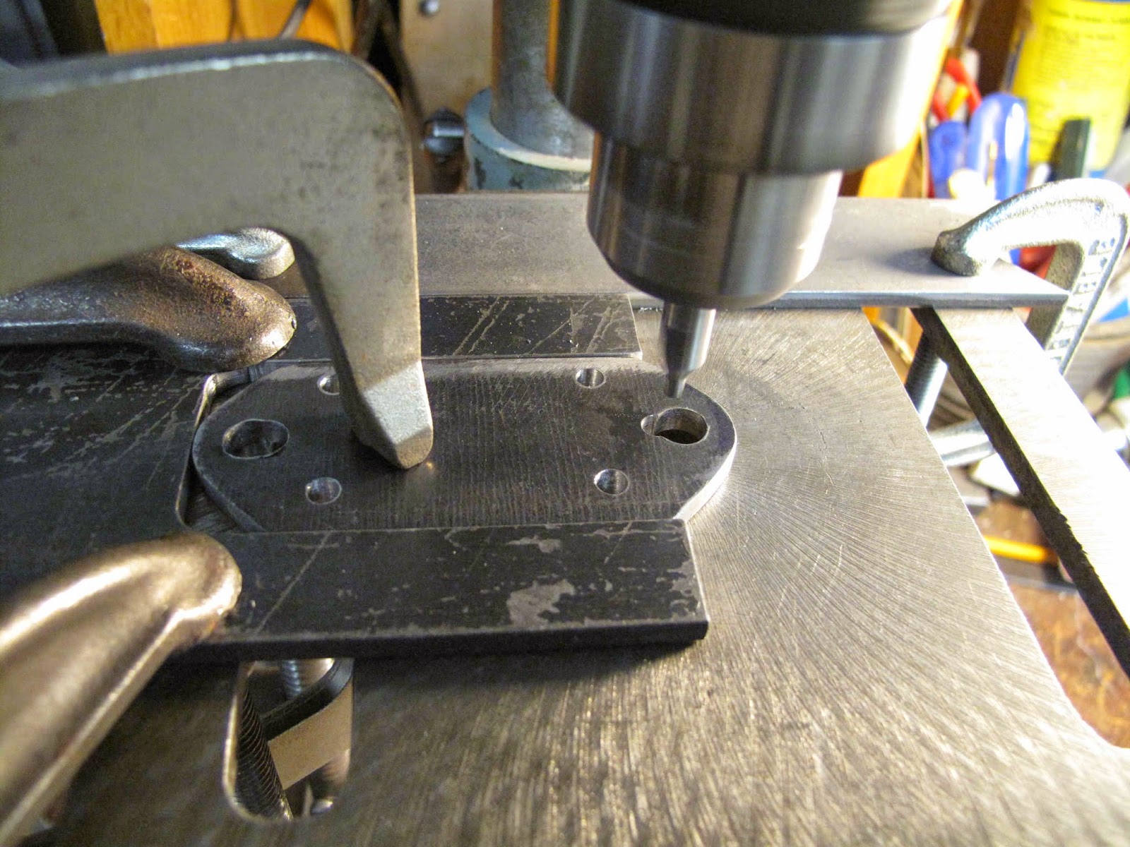
 The next step was to increase the size of the bolt holes.  I made a fixture to hold the flange while drilling.  I've grown tired of parts whirling around the drill bit.
To locate the fixture I put the 3/16" bit in the drill and lowered it to the outer hole, then clamped the fixture to the table.


 Change the bit to 5/16", clamp the part and re-drill the hole.

 I then lowered the table and re-positioned the fixture. so I could drill the hole with a 21/64" drill.
 To reduce the filing needed to finish shaping the hole  I then did the same process for the inboard hole.

The difference is I want the edge of the 5/16" drill to line up with the edge of the 3/16" hole.

I started by using the 3/16" bit to locate the hole like with the outboard hole.

With the bit in the hole I clamped a guide fence along the back of the fixture.  The pocket in the fixture is reversed to hold the flange from moving away from the drill.  You really need the short center bit to do this.  A long bit bends too much.  It might even break.

With the fence holding the fixture from moving fore and aft I measured the position of the fixture along the fence. I added 1/16" to this measurement and locked the vernier as a gauge to position the fixture 1/16" to the left so the 5/16" bit would now drill in the correct location.

Slide the flange to the left in the fixture, clamp it and drill.

After cutting out the inlet hole I'll finish this oval in the vise with a 5/16" rat tail file.