Sunday, January 28, 2024

Band Sawing Mounting Flange Blanks

 I made the original mounting flanges from 1-1/2" x 3/16" mild steel bar stock.  The only cuts I made were the angled cut at each end.

I'm cutting 4 flanges from the piece of 1/4" x 6" x 6" stainless plate I bought from McMaster.  This means I also have to make at least 1 cut 3-3/8" long on the long side.  

The sawn sides get smoothed up on the belt sander with an 80 grit belt.

Once the sides are smooth and 1-1/2" apart the end cuts are made and cleaned up on the belt sander.  I find it much harder to score a line on the stainless then mild steel or Normalized 4130.


I'm also finding the cut speed is about 4 to 4-1/2 minutes for the long cut.  That seems about the same as when I cut 3/16" 4130.

The bad news is the blade goes dead in 8-10" of cutting.  I still have plenty of 1/4" coil stock to make blades but that's more time and money.  I need to find some 1/4" x 1-1/2" bar stock.  McMaster has some 1/2" long life blade stock but it's about $250 for 50 feet.

The next step was to center punch the holes.

Unfortunately my 3/16" duplicating punch is dull.  We'll order some more tomorrow, maybe not from McMaster.


One Test Shell Made With Revised Procedure for Inlets - Without Sidewall Stretch

Based on my experiments in the last post the first step is to remove the Tall inlet bottom blocks and install the Shorter ones.


The piece of Oak I used to make the shorter blocks wasn't as long as the tall blocks so I used a piece of a Cedar Shim at the far end of the block to hold it in position.  The sheet metal ends before the shim so it never gets hammered forming the shell.


Rather than use an expensive piece of Stainless Steel, I used one of the blanks I had previously made from 1018 Mild Steel.  I didn't make any changes to the shape of the blank, installed it in the form block, clamped it and followed to the shaping processes I used for the older shells.

Once I had the inlets formed with the rounded wooden tool and a good start on the body of the shell I stopped and removed the shell from the form the block.


The inlet bottoms are nicety rounded.  Each one is slightly different due to how the metal slid into the form block cavities.

With the original inlet bottom blocks back in the form block the shell inlet ends now set up off the clamping surface because of the rounded bottoms.  We need to flatten the bottoms a little, moving some steel into the corners, just enough to bolt the clamp board back in place.


For reasons I can't remember I have an older, smaller inlet forming tool, probably covered in an old post. The wide one measures 1-27/32" wide.  The narrow one measures just over 1-5/8", about 1/4" smaller than the wide one.
The wide one is too tight of a fit to use without the steel securely clamped in place.

The small one worked perfect to flatten the bottom nearly to the finished shape without it being clamped.  I think a piece of Oak or Ash with the same bottom shape would also work.


The shell now sets down close enough to the block to allow the clamping board to be re-installed.


The inlet shapes shapes are not yet finished and hold the clamp board up a little.  With a little tightening of nuts that could be installed the board slowly pulled down tight enough to get all nuts on and tight enough to finish shaping the inlets with the wide tool.


Before finishing the rest of the shell I worked all the inlets to their finished shape as I had done on the earlier shells.  I then followed th old procedures to finish shaping  the shell.

A square flat bottom inlet without any thinning or stretch marks in the side walls.  They still measure 0.032" thick, so we have all the strength the shell can give us to support he manifold on a shaking motor.

This should work as well with the expensive Stainless Steel.  Now back to working on the 1/4" thick flanges that get welded to these inlets.


[


Monday, January 22, 2024

Exhaust Manifold Inlets


When I formed the rectangular inlet on the stainless shell sample I took a guess at how much extra metal to draw into the form block to get the correct amount of metal to form the rectangular shape.  I had an idea how to do it more precisely.  

The objective is to work out how tall of a hardwood block is needed under the steel so the steel hits the block just as the curved loop is long enough to form the finished rectangular shape.  I think I'd rather be just a tiny bit short then being a little too long.
I started by sheering 2 strips of 0.032" 1018 steel.  It's cheaper to play with and the mechanical properties aren't that different from the 0.032" stainless.

I formed the first strip around the tool that I used for forming (hammering) the inlets in the form block. I drew some lines on the strips so I could align the tool close to the center of the strip.

I gently hammered the strip against the too to form the bottom of the "U" shape.


I clamped the "U" shaped piece in the form block against the original limiting block. With it securely clamped I gently hammered the legs down to the clamping surface of the form block.


Nicely formed without stretching the side walls.  That's the goal for the 4 inlets in each shell half.


For figuring out the curved part I worked backwards.  I held the squared piece against the forming tool and marked where the legs ended.  This allowed me to clamp the second strip with each end aligned to it's mark.  Then I folded each 90 degree bend around the tool.

The next step was to form the bend in the middle so it follows the curve of the tool I used to pound the metal into the form block.


We're getting close to being finished with the piece back in the form block.  I had marked the block so I could see that the flat legs are the correct length.  Therefore the curved piece is the right length from bend to bend.


I put the clamping board back on and lightly tightened the nuts.  Then I wiggled the square forming tool into the gap just enough to hold the metal corner bends tight to the block while tightening the clamping nuts.
OK, were ready to measure from the base board to the bottom of the bend.  I used my Vernier to measure so it's really measuring to the top side of the bottom of the bend, therefore I need to subtract 0.032", the metal thickness, from my measurement.

The Vernier reads 1.621" so the 4 blocks need to be 1.589" thick or about 1-19/32".  I've got a block of oak just right for this.


Saturday, January 20, 2024

Stainless Steel Exhaust Manifold

 Wings and Wheels Museum at Poplar Grove, Illinois has built a replica Curtiss Jenny.  They had help from EAA Chapter 1414 as well as access to the original Curtiss Drawing.  They flew it to Oshkosh in 2022.  I need to find out if they had access to the exhaust manifold drawings.


I built them a set of exhaust manifolds for their motor.  They've had a few problems and I'm slowly working on how to solve them.  Their main request is to make them from 321 Stainless Steal instead of 1018 Mild Steel.

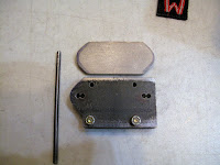
The first problem was a flange which broke.  The other problem was considerable internal corrosion.  Clearly stainless steel solves the corrosion problem.  I didn't use stainless to make these because although it was invented in 1913 it wasn't readily available until well after WWI.  My other reason was that I had no experience with stainless steel.  
I may never be a big fan of stainless steel.  It has some obvious advantages for reducing corrosion.  The 321 composition was created to make a more weldable material than the more common 304 stainless.  One disadvantage of 321 stainless is it's much higher cost.  A 12"x12" piece of 0.032" thick 321 stainless cost me $25.  I bought a 4 ft x 8 ft sheet of 0.032" 1018 steel for $35.  The set of manifolds take 4 pieces 12" x 30" and 4 pieces 12" x 12".
The other disadvantage is that it not as strong, more of an issue for the flanges.
The Yield Strength is:
1005 Low Carbon Steel   41,000 psi
1018 Cold Rolled Steel    53,700
4130N Chromoly Steel    75,000
321   Stainless Steel         25,000

The last disadvantage is that stainless is reported to be more difficult to weld.  There is a fair amount of welding on each manifold.

Having said all that I've bought some pieces of 321 stainless and am learning how to make the manifolds from it.

My first task was to shear some strips to Spot Weld and do the edge fold.  My shear won't shear the 0.032" thick sheet.  It has no problem with the 0.032" 1018 sheet steel.  I used my snips cut some strips 1/2" wide to experiment with.

I spot welded some pieces then tried prying them apart.  They were very strong, I could not pry them apart.

Then I spot welded pieces with one piece longer than the other and hammered the long piece over the short to make the folded edge on the shells.  I had no problem doing it and find no cracking, looking with a 10x glass.

The next test was to cut out a portion of the shell blank and hammer it to shape.  It formed fine and I think will work fine on a full piece.


The way I've been forming the rectangular inlet causes the steel in the side walls to be stretched.  Everywhere else on the shell the steel slides into the hole in the form bloc, therefore it doesn't thin the metal by stretching.  These side walls need to be as strong as possible to help support the manifold when the flange is bolted to a shaking motor.
I had made some hardwood blocks for the inlet of each tube.  These blocks limit the depth of the wide flat part.  This controls the height of the rectangle so it matches the outlet of the cylinder port.

By leaving these out I was able to pull the metal further into the block.  This leaves a round bottom, like the tubes.  Then I took the block apart, added the blocks and reassembled it so I could square up the rounded bottom.  I need to make some new blocks to limit the depth of the round bottom, so it has just enough length to form the square bottom.  This method got rid of the stretching in the sides.

The 2 tubes came out really well.  I should be able to form the shells and spot weld them together.  I need to experiment with welding the edges where the flange isn't wide enough to spot weld.  My Dillon torch claims to weld stainless and my wife got me a small TIG welder for Christmas.  We'll see what works best.
I'm working on the flanges now.  When I made the mild steel ones I bought 1-1/2" wide 3/16" bar stock.  I have only found 2-1/2" wide bar stock in 321 stainless.  I'm making them from 1/4" instead of 3/16" thick because of the lower strength of the stainless.  The lack of 1-1/2" bar stock means a lot more bandsaw time, but it seems to cut OK.

I'll also have to modify my fixtures for drilling and cutting the holes.