Tuesday, March 31, 2015

Exhaust Manifolds Finished


 The finished Manifolds look like what I expected the original would have been.  I used the Rust-Oleum 2000 degree primer and black paint for the bottom, around the flanges, the inlets and inside the outlet.   I thought this would let me get better rust prevention along the seams and other areas which would be hard to cover well with the stove black.   For the Top Surfaces I used the stove black because it seems easier to freshen up in service than paint.  After flying just rub a little Stove Black on the shell.  I believe the originals were finished with the stove black.  Let's face it 2000 degree paint probably didn't exist 100 years ago.

 I tried both the Imperial Stove Polish Liquid Black and the William's Stove Polish.  They both contain carbon and graphite so the look is the same and the coverage seems the same.  The William's is more of a paste and I think it will work better for touch up in service.  The Imperial is a liquid so it was easier to apply, though a little messier.
So that the look would be the same on the top and bottom I lightly wiped the bottom with it also.  Because of the graphite, the finish has a slight metallic sheen.

I like it.

You'll notice one naked manifold hanging there.  I started to prime it and realized I hadn't finished welding it.  I think the rain stopped me and I missed it the next day.  I'll finish it the next nice day.

This has been a long process but they came out great.  It's really exciting to see them done.

Thursday, March 26, 2015

Exhaust Manifold Welding is Done


All the fabrication work is done on the 3 sets of exhaust manifolds.  The flanges are welded on, the excess shell trimmed at the inlets and all the weld scale, etc. sand blasted.

They are now ready for painting.

This is so cool,

Thursday, March 12, 2015

Weld Mounting Flanges To first Exhaust Manifold Shell


 To help control the 18 degree upward tilt of the manifold I bolted some pieces of 1" angle to the side of the 1-1/2" angle base.  I then clamped on some pieces of wood with marks for where the center of the seam should line up to get the angle.  This way the shell can move if the welds are pulling it as they cool and I can see what is happening.  I don't think I could build my fixture rigid enough to hold everything without much heavier angle for the base.

I started welding by tacking all the corners (16 tacks). I started with the outer corners of each tube.  I did 2 corners at one end then moved to the opposite end and did 2 corners.  Then did 2 corners on the outer end of an inner tube followed by the outer end of the other inner tube.  Then I used the same pattern for the inner corners of each tube.  With all the corners tacked I then welded the top and bottom edges of the tubes to the flanges in the same pattern.

 This all worked fine and the shells held the 18 degree angle very precisely.  I found it easy to tip the vise to hold everything at convenient angles to weld the joints.

 The thing I hadn't thought enough about was the heat shields which are welded to the top to protect the valve springs.  On the next shell I'll try spot welding them on and possibly welding the edge completely before installing the flanges to weld.  I either had the edge too close to the flange and it was hard to get the puddle to form all the way to the bottom or the gap was too big and it was like welding two parts which just happened to be near each other.

The process I used for them was to clamp the shield to the shell, tack the corners, remove the clamp, and make the weld to the shell and the flange.


 With the welding done the top and bottom of the tubes, the seam on the manifold is still aligned with the marks, as it was at the start.

The top side was easier to weld because the heat box as not in the way but it had the added problem of the shields.

Once the top and bottom were welded the fixture was removed so there would be room to weld the sides without the nuts in the way.  This worked fine and the flanges are all still aligned and flat.


A complete manifold assembly.  The ends of the tubes need to be trimmed to the face of the flanges.  After that, sand blasting and paint, etc.

Saturday, March 7, 2015

Exhaust Manifold Flange Welding Fixture

While making the exhaust flanges I broke one of my last 3/16" center drills and lost the last bit for my Vargus de-burring tool, so off to McMaster-Carr for some more center drills, bits for the de-burring tool and a new tool holder for it.  The old holder was so worn after 40 years that the bit would not stay in.  I asked for a new catalog, knowing I just don't buy enough anymore to rate a 4000 page tome like this.  After much begging and offers to buy one or bribe a company official to get one they found one with a slightly damaged cover.  It arrived today.  It's wonderful.  This will make finding things I need so much easier.  The pages are bigger and it's over 1000 pages more than my old one.  Oh yeah, the new tools work great also.

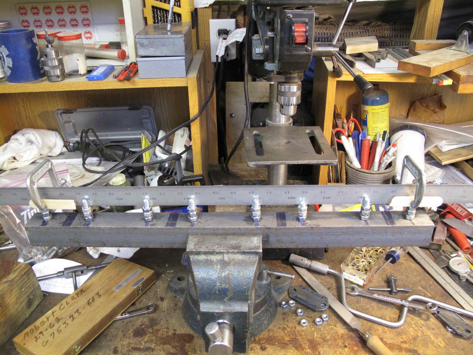
 To hold the Flanges in the proper position, on the Manifold Shell, while welding I'm making a simple fixture from a 24" piece of 1-1/2" x 1/8" steel angle and some 5/16" bolts.  The Cylinders are located 6-1/4" on centers and the exhaust studs are 2-5/8" on centers.  I tapped the holes in the angle to get a snugger fit with the grade 2 bolts and then put a jamb nut tight to the angle.

The flanges rest on a stack of 2 nuts tightened together with room left at the end for the flange and a nut to hold it tight while welding.

 To get the top of all the support nuts on a line I started by setting the nuts on the 2 end bolts first.  This got the nuts the correct distance from the end of the bolts.  Then it was just a matter of setting the others on the line.

At first I thought I could just clamp a straight edge to the 2 end bolts and adjust the rest to just touch it.  It turns out you can't clamp it tight enough. You can create a lot of pressure when tightening the nuts and it pushes the straight edge away from the end nuts.
It also takes some care to tighten the top nut down while tightening the bottom one up to get the top nut just on the line.

 The solution turned out to be easy and fairly quick.  I let the straight edge rest on the 2 end nuts with all the others below the line.  I then started with a nut just inboard of an end and raised it until the straight edge rocked on it.  While holding the closest end down, I adjusted the nut down until the far end of the straight edge just touched it's end nut.

I then tightened the nuts together and readjusted them as needed until they just touched the straight edge while not letting it rock.

Then work on the same nut at the opposite end and slowly work toward the middle..


 It worked great.  The engine side of the flanges are all in line within a couple thousandths of an inch.
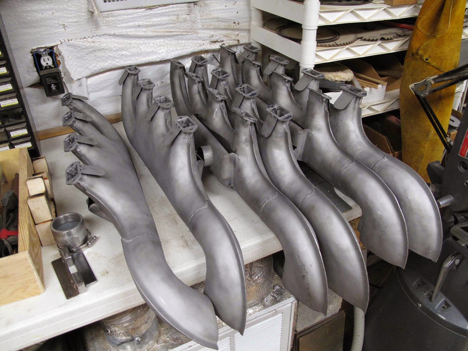
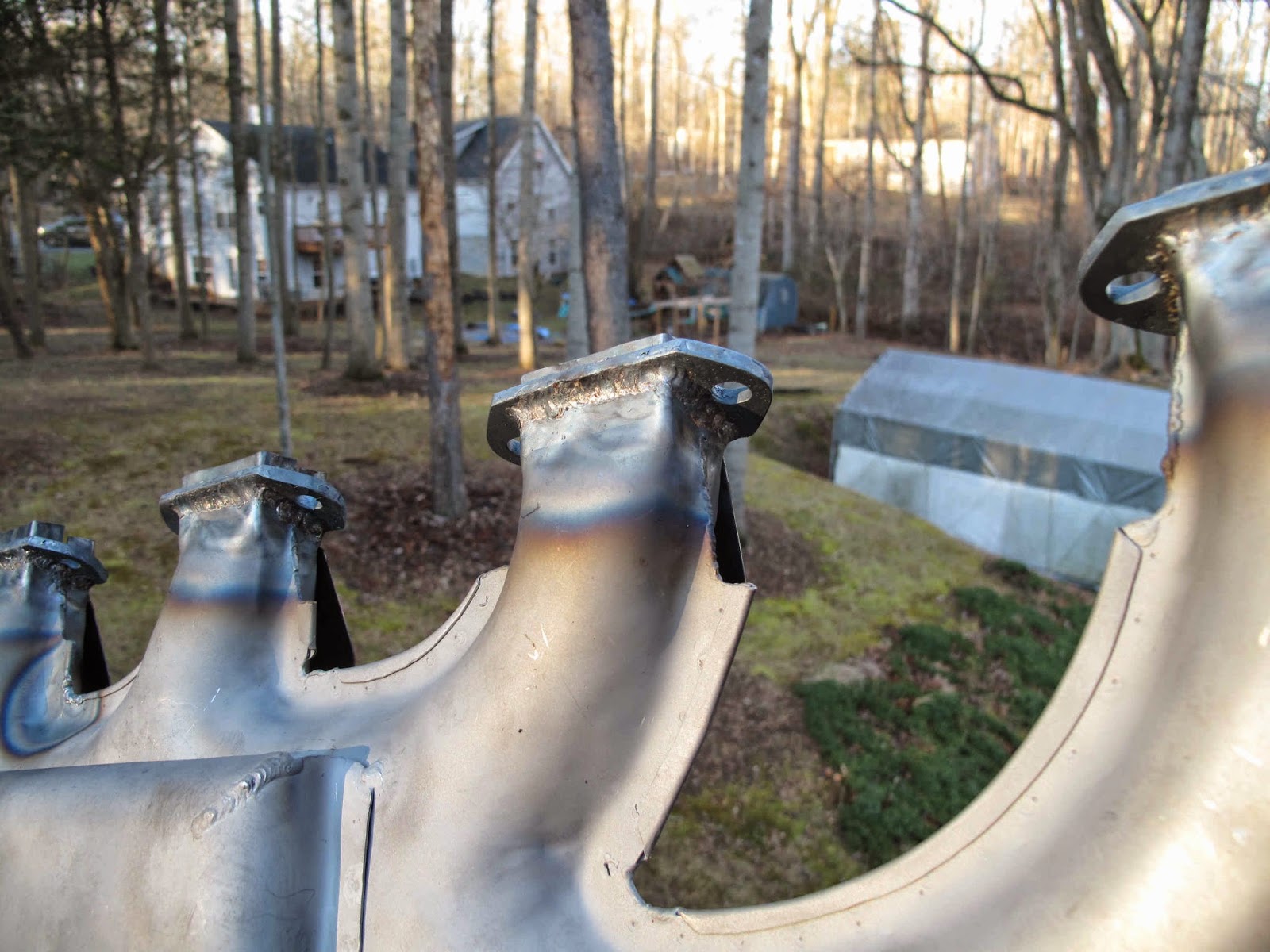
 I found it easier to assemble the flanges to the shell and then mount them to the fixture.  The ends of the shell line up the flanges while the fixture holds their faces on a plane so the gaskets can seal.

I need to add a support to hold the 18 degree angle while welding.  The weather is warming so I may be able to start welding soon.

Friday, March 6, 2015

Exhaust Manifold Flanges - Ready to Weld

I was so excited that the cutting operation worked and learning about any issues using the torch that I forgot to check that the guides were set square and adjusted to make the correct width opening.  As a result I needed to do some filing to open the holes a little.

 To make it easy I drew 18 degree guide lines on the top of the vise and then worked one end of the flange, flipped it over and worked on the other end.

I bought a cheap ($33) Bandfile from Harbor Freight.  It's a 1/2" wide belt sander.  I used it to quickly cut down the steel.

 With the ends close to size I used a 10" bastard file to finish them so my gauge block fit.

I made the block from a piece of 1/2" x 1" bar stock 1-7/8" long.  I carefully ground the ends square so I could check both the size of the opening and, to make sure the ends were parallel and square to the sides.


 The Bandfile had a small problem.  The backing plate/guides for the belt were made of rubber and the cloth belt quickly ground them to dust.  They were just glued on so I made new ones from 0.090" 4130 steel and super glued them on with a gel glue.  I radiused the ends to save wear on the belt.  They work great.  The belts which came with it worked but were a little wimpy.  They are 18" belts so I bought an 3" x 18" P60 Shop Smith Ceramic Belt and cut it into 1/2" strips, much better.  You just cut the cloth belt on the inside with a knife with break-away blades.  These are the same belts I like for metal work on the Shop Smith and they work great.

The Bandfile really helped clean up the sides since it's hard to hold them and do much filing.


 I made a gauge 1/1/8" wide, 3/8" thick, with an 18 degree cut on the end to check the gap between the 2 angled sides.

When the gauge fits flush to the surface the gap is wide enough for the manifold to fit.

 The flanges fit great on the manifold.  Now I need to finish the fixture to hold the flanges in position while welding them to the manifold shell.


Monday, March 2, 2015

Exhaust Manifold Flanges - Inlet Opening Side Cutting


 The weather warmed up to 50 degrees.  A nice afternoon to work on cutting the sides of the inlet openings in the flanges.  I found the parts would set in the fixture without clamping them down while cutting.

I also found it was easier to heat the corner hole to start the cut by tipping the torch up perpendicular to the flange and, then lowering it to the 18 degree angle before starting the cut.

The cuts came out great but I forgot I needed to make a final adjustment to the front roller guides after the first part.  The guides were about 3/32" to close together so all these parts will need to be filed to correct my forgetfulness.  Based on how these parts fit the manifold shells I'll make some final adjustments to all the guides on both fixtures.

It's cool that it all works so well.

Thursday, February 26, 2015

Exhaust Manifold Flanges - Inlet Side Cut Fixture

The 2 side cuts for the inlet openings needed a fixture to get a straight cut and to hold the torch at an 18 degree angle while making the cuts..  For the top and bottom cuts the angle is formed by tipping the plane of the cut 18 degrees from perpendicular while holding the torch perpendicular to the flange in the plane of the cut.  For the sides the 18 degree angle is in the plane of the cut while the plane of the cut is perpendicular to the flange.

 Just like the other fixture I'm using the vise to hold the fixture so again I started with a piece of steel angle clamped in the vise.  The flange sets on the angle while cutting.


I cut 2 slots in the piece of angle to provide clearance while making the cuts.  I left the center piece so I can clamp the flange in place while cutting.

 To locate the flange for cutting I made a pocket for the flange to set in.  I had wanted to use a pin in the bolt hole as a stop side to side like I did in the other fixture but there wasn't enough room.  The side cuts are too close to the bolt holes.


The pocket will get held to the angle by the screws which hold the roller guides in position.

 As with the other fixture, the side roller guides are pieces of 0.050" steel with slots for the screws to allow side to side adjustment.

In this case I will use the left hand guide for the cut on the left side of the flange and and the right guide for the right side cut.

 With the other fixture the the side rollers are adjusted to tip the cutting tip to the side.  With this fixture the front (side) rollers are adjusted even to hold the tip square.  To get the 18 degree angle the rear roller needs to be 1.71" lower than the front rollers.

To do this I made an "L" shaped table which is attached to the back of the angle.  The vertical slots allow the height to be adjusted to get the 18 degree angle.  The side slots allow the side guides to be adjusted to position the rear roller.  They also hold the 2 pieces together to form the table.


 As with the front roller guides the rear roller uses the left hand guide for the left side cut in the flange and the right guide for the right side cut.

I need to adjust all these movable parts, wait for the current snow storm to end and then try this out.